 -Schneider Electric 1")
-Schneider Electric 2")
-Schneider Electric 3")
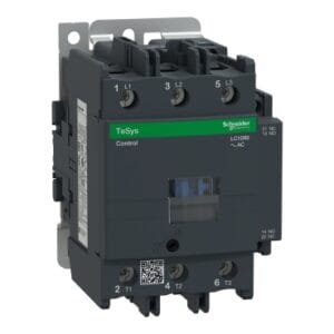
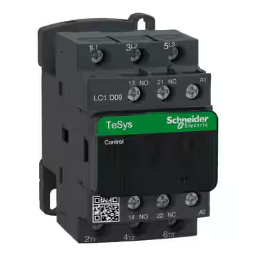
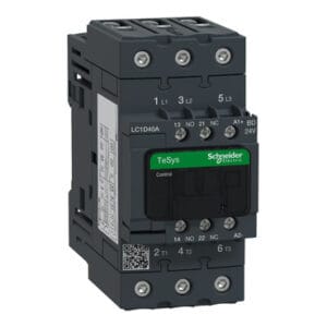
TeSys D contactors have been designed for perfect integration into control systems. They can be used to create motor starters for almost any type of application. TeSys D contactors are available in 13 contactor ratings for inductive motor applications up to 150 full-load amps and resistive loads up to 200 amps. This 40A inductive 3 pole IEC contactor can be mounted on DIN rail or mounted directly to a panel. Contactors have both Horsepower and Kw motor rating for international acceptance.
Contactor is rated for 10HP at 200 to 208VAC, 10HP at 240VAC, 30HP at 480VAC and 30HP at 600VAC three phase. Contactor is also rated for 3HP at 115VAC and 5HP at 240VAC single phase. When used with a 480VAC up to 110A circuit breaker, this contactor can have a SCCR up to 100kA. When used with up to a 600VAC 90A Class J or CC fuse, this contactor can have a SCCR up to 100kA. Contactor is supplied with a 24 VDC coil with transient suppressor module.
Contactor has one normally open and one normally closed auxiliary contact built-in as standard. The NC contact is mirror certified. Screw clamp terminals are used for load and auxiliary connections. An extensive line of accessories makes it easy to meet the requirements of most applications. The contactor is 4.80 inches tall, 2.17 inches wide and 4.72 inches deep. It weighs 1.87 lbs. Contactor is certified to UL, CSA, IEC, CCC, EAC and Marine standards. Contactor also meets the requirements of RoHS/REACh making it a Green Premium product.
| Specifications | |
| Main | |
| Range | TeSys |
| TeSys Deca | |
| Range of Product | TeSys Deca |
| Product or Component Type | Contactor |
| Device short name | LC1D |
| contactor application | Resistive load |
| Motor control | |
| Utilisation category | AC-4 |
| AC-1 | |
| AC-3 | |
| AC-3e | |
| poles description | 3P |
| [Ue] rated operational voltage | Power circuit <= 690 V AC 25…400 Hz |
| Power circuit <= 300 V DC | |
| [Ie] rated operational current | 60 A (at <140 °F (60 °C)) at <= 440 V AC AC-1 for power circuit |
| 40 A (at <140 °F (60 °C)) at <= 440 V AC AC-3 for power circuit | |
| 40 A (at <140 °F (60 °C)) at <= 440 V AC AC-3e for power circuit | |
| [Uc] control circuit voltage | 24 V DC |
| Complementary | |
| Motor power kW | 18.5 kW at 380…400 V AC 50/60 Hz (AC-3) |
| 11 kW at 220…230 V AC 50/60 Hz (AC-3) | |
| 22 kW at 415…440 V AC 50/60 Hz (AC-3) | |
| 22 kW at 500 V AC 50/60 Hz (AC-3) | |
| 30 kW at 660…690 V AC 50/60 Hz (AC-3) | |
| 9 kW at 400 V AC 50/60 Hz (AC-4) | |
| 18.5 kW at 380…400 V AC 50/60 Hz (AC-3e) | |
| 11 kW at 220…230 V AC 50/60 Hz (AC-3e) | |
| 22 kW at 415…440 V AC 50/60 Hz (AC-3e) | |
| 22 kW at 500 V AC 50/60 Hz (AC-3e) | |
| 30 kW at 660…690 V AC 50/60 Hz (AC-3e) | |
| Maximum Horse Power Rating | 5 hp at 230/240 V AC 50/60 Hz for 1 phase motors |
| 10 hp at 230/240 V AC 50/60 Hz for 3 phase motors | |
| 30 hp at 575/600 V AC 50/60 Hz for 3 phase motors | |
| 10 hp at 200/208 V AC 50/60 Hz for 3 phase motors | |
| 3 hp at 115 V AC 50/60 Hz for 1 phase motors | |
| 30 hp at 460/480 V AC 50/60 Hz for 3 phase motors | |
| Compatibility code | LC1D |
| Pole contact composition | 3 NO |
| Protective cover | With |
| [Ith] conventional free air thermal current | 10 A (at 140 °F (60 °C)) for signalling circuit |
| 60 A (at 140 °F (60 °C)) for power circuit | |
| Irms rated making capacity | 140 A AC for signalling circuit conforming to IEC 60947-5-1 |
| 250 A DC for signalling circuit conforming to IEC 60947-5-1 | |
| 800 A at 440 V for power circuit conforming to IEC 60947 | |
| Rated breaking capacity | 800 A at 440 V for power circuit conforming to IEC 60947 |
| [Icw] rated short-time withstand current | 320 A 104 °F (40 °C) – 10 s for power circuit |
| 720 A 104 °F (40 °C) – 1 s for power circuit | |
| 72 A 104 °F (40 °C) – 10 min for power circuit | |
| 165 A 104 °F (40 °C) – 1 min for power circuit | |
| 100 A – 1 s for signalling circuit | |
| 120 A – 500 ms for signalling circuit | |
| 140 A – 100 ms for signalling circuit | |
| Associated fuse rating | 10 A gG for signalling circuit conforming to IEC 60947-5-1 |
| 80 A gG at <= 690 V coordination type 1 for power circuit | |
| 80 A gG at <= 690 V coordination type 2 for power circuit | |
| Average impedance | 1.5 mOhm – Ith 60 A 50 Hz for power circuit |
| Power dissipation per pole | 2.4 W AC-3 |
| 5.4 W AC-1 | |
| 2.4 W AC-3e | |
| [Ui] rated insulation voltage | Power circuit 600 V CSA |
| Power circuit 600 V UL | |
| Signalling circuit 690 V IEC 60947-1 | |
| Signalling circuit 600 V CSA | |
| Signalling circuit 600 V UL | |
| Power circuit 690 V IEC 60947-4-1 | |
| Overvoltage category | III |
| Pollution degree | 3 |
| [Uimp] rated impulse withstand voltage | 6 kV IEC 60947 |
| Safety reliability level | B10d = 1369863 cycles contactor with nominal load EN/ISO 13849-1 |
| B10d = 20000000 cycles contactor with mechanical load EN/ISO 13849-1 | |
| Mechanical durability | 10 Mcycles |
| Electrical durability | 0.7 Mcycles 60 A AC-1 <= 440 V |
| 1.5 Mcycles 40 A AC-3 <= 440 V | |
| 1.5 Mcycles 40 A AC-3e <= 440 V | |
| Control circuit type | DC standard |
| Coil technology | Built-in bidirectional peak limiting diode suppressor |
| Control circuit voltage limits | 0.1…0.3 Uc -40…158 °F (-40…70 °C) drop-out DC |
| 0.75…1.25 Uc -40…140 °F (-40…60 °C) operational DC | |
| 1…1.25 Uc 140…158 °F (60…70 °C) operational DC | |
| Inrush power in W | 19 W 68 °F (20 °C)) |
| Hold-in power consumption in W | 7.4 W 68 °F (20 °C) |
| Operating time | 50 ±15 % ms closing |
| 20 ±20 % ms opening | |
| Time constant | 34 ms |
| Maximum operating rate | 3600 cyc/h 140 °F (60 °C) |
| Connections – terminals | Control circuit: screw clamp terminals 2 0.00…0.00 in² (1…2.5 mm²) – cable stiffness: flexible with cable end |
| Control circuit: screw clamp terminals 1 0.00…0.01 in² (1…4 mm²) – cable stiffness: flexible without cable end | |
| Control circuit: screw clamp terminals 2 0.00…0.01 in² (1…4 mm²) – cable stiffness: flexible without cable end | |
| Control circuit: screw clamp terminals 1 0.00…0.01 in² (1…4 mm²) – cable stiffness: flexible with cable end | |
| Control circuit: screw clamp terminals 1 0.00…0.01 in² (1…4 mm²) – cable stiffness: solid without cable end | |
| Control circuit: screw clamp terminals 2 0.00…0.01 in² (1…4 mm²) – cable stiffness: solid without cable end | |
| Power circuit: screw connection 1 0.00…0.05 in² (1…35 mm²) – cable stiffness: flexible without cable end | |
| Power circuit: screw connection 2 0.00…0.04 in² (1…25 mm²) – cable stiffness: flexible without cable end | |
| Power circuit: screw connection 1 0.00…0.05 in² (1…35 mm²) – cable stiffness: flexible with cable end | |
| Power circuit: screw connection 2 0.00…0.04 in² (1…25 mm²) – cable stiffness: flexible with cable end | |
| Power circuit: screw connection 1 0.00…0.05 in² (1…35 mm²) – cable stiffness: solid without cable end | |
| Power circuit: screw connection 2 0.00…0.04 in² (1…25 mm²) – cable stiffness: solid without cable end | |
| Tightening torque | Control circuit 15.05 lbf.in (1.7 N.m) screw clamp terminals flat Ø 6 mm |
| Control circuit 15.05 lbf.in (1.7 N.m) screw clamp terminals Philips No 2 | |
| Power circuit 70.81 lbf.in (8 N.m) EverLink BTR screw connectors 0.04…0.05 in² (25…35 mm²) hexagonal 0.16 in (4 mm) | |
| Power circuit 44.25 lbf.in (5 N.m) EverLink BTR screw connectors 0.00…0.04 in² (1…25 mm²) hexagonal 0.16 in (4 mm) | |
| Control circuit 15.05 lbf.in (1.7 N.m) screw clamp terminals pozidriv No 2 | |
| Power circuit 22.13 lbf.in (2.5 N.m) screw clamp terminals pozidriv No 2 | |
| auxiliary contact composition | 1 NO + 1 NC |
| Auxiliary contacts type | Mechanically linked 1 NO + 1 NC IEC 60947-5-1 |
| Mirror contact 1 NC IEC 60947-4-1 | |
| Signalling circuit frequency | 25…400 Hz |
| Minimum switching voltage | 17 V for signalling circuit |
| Minimum switching current | 5 mA for signalling circuit |
| Insulation resistance | > 10 MOhm for signalling circuit |
| Non-overlap time | 1.5 ms on de-energisation between NC and NO contact |
| 1.5 ms on energisation between NC and NO contact | |
| Mounting Support | Rail |
| Plate | |
| Environment | |
| Standards | CSA C22.2 No 14 |
| EN 60947-4-1 | |
| EN 60947-5-1 | |
| IEC 60947-4-1 | |
| IEC 60947-5-1 | |
| UL 508 | |
| IEC 60335-1 | |
| Product Certifications | CCC |
| CSA | |
| GOST | |
| UL | |
| IP degree of protection | IP20 front face IEC 60529 |
| Protective treatment | THIEC 60068-2-30 |
| Climatic withstand | IACS E10 exposure to damp heat |
| IEC 60947-1 Annex Q category D exposure to damp heat | |
| Permissible ambient air temperature around the device | -40…140 °F (-40…60 °C) |
| 140…158 °F (60…70 °C) with derating | |
| Operating altitude | 0…9842.52 ft (0…3000 m) |
| Fire resistance | 1562 °F (850 °C) IEC 60695-2-1 |
| Flame retardance | V1 conforming to UL 94 |
| Mechanical robustness | Vibrations contactor open 2 Gn, 5…300 Hz) |
| Vibrations contactor closed 4 Gn, 5…300 Hz) | |
| Shocks contactor closed 15 Gn for 11 ms) | |
| Shocks contactor open 10 Gn for 11 ms) | |
| Height | 4.80 in (122 mm) |
| Width | 2.17 in (55 mm) |
| Depth | 4.72 in (120 mm) |
| Net Weight | 2.04 lb(US) (0.925 kg) |
| Ordering and shipping details | |
| Category | US10I1222358 |
| Discount Schedule | 0I12 |
| GTIN | 3.38912E+12 |
| Returnability | Yes |
| Country of origin | FR |
| Packing Units | |
| Unit Type of Package 1 | PCE |
| Number of Units in Package 1 | 1 |
| Package 1 Height | 2.44 in (6.200 cm) |
| Package 1 Width | 5.39 in (13.700 cm) |
| Package 1 Length | 5.98 in (15.200 cm) |
| Package 1 Weight | 34.53 oz (979.000 g) |
| Unit Type of Package 2 | S02 |
| Number of Units in Package 2 | 10 |
| Package 2 Height | 5.91 in (15.000 cm) |
| Package 2 Width | 11.81 in (30.000 cm) |
| Package 2 Length | 15.75 in (40.000 cm) |
| Package 2 Weight | 22.22 lb(US) (10.080 kg) |
| Unit Type of Package 3 | P06 |
| Number of Units in Package 3 | 160 |
| Package 3 Height | 29.53 in (75.000 cm) |
| Package 3 Width | 23.62 in (60.000 cm) |
| Package 3 Length | 31.50 in (80.000 cm) |
| Package 3 Weight | 395.25 lb(US) (179.280 kg) |
| Contractual warranty | |
| Warranty | 18 months |
Reviews
There are no reviews yet.